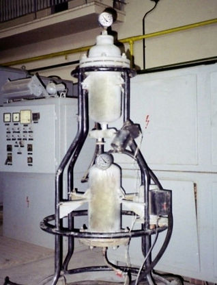
INJECT Installation
Pilot Installation for Powder Material Injection into the Metallurgical Melts
Description, main components, technical characteristics of the installation
Injection methods effectively reduce the sulphur content of the molten steel bath. In this method, a strong desulphurizing reagent in the form of fine powder is injected (through a lance) in the refined steel bath along with an inert gas (argon) as carrier.
Injection reagent may be metallic like calcium, magnesium or the other form like lime, calcium carbide, calcium silicide and magnesium coke. Desulphurize agents powder are used for injection (CaSi, CaC2, Mg, CaO + Mg etc.) injection achieved in liquid steel using a carrier gas (Ar, N2) through a lance protected by ceramic rings.
Injection cycle time is about 20...50 minutes upon the aim and final chemistry, and the rate of injection of the powdery material ranges between 2...4 kg / ton of melt.


On the injection stand, injection lance is inserted through the furnace cover is lowered and immersed into the melt. Desulphurization agents are injected along with the flow of argon. Argon bubbles produce stirring of the molten steel and promoting desulphurization. Stirring also provides thermal and chemical homogenization of the melt.
The more interfacial area of contact of particles with the steel bath leads to very efficient interaction of the reagent with the bath. Desulphurization takes place in a short time of about 8...10 minutes and the bath looses 30...35ºC temperature. The sulphur content must not exceed ten parts per million (ppm).
To ensure that this level of desulphurisation requires a high level of technological know-how and sophisticated secondary metallurgy.
The basic process, that involves injecting powdered material gasified in molten steel, was developed as a treatment TN by Thyssen & Niederrhein AG. According to process TN (Thyssen & Niederrhein AG) process with the widest industrial application in this field, are injected calcium compounds and magnesium in the steel bath, using, as a carrier gas, argon.
Main components of the installation
Pilot installation in the ERAMET laboratory for the injection of powder materials is designed to refine molten metal by introducing in them, with an inert gas, of powder materials adequately for a metallurgical process.
Conceptually, the pilot installation was designed to streamline the process of fluidized, by coupling in one system of the most used types of dispersers for powder: with pusher, with fluidiser and with vibration
The main components of the pilot installation for injection of powder materials are:
a. container tank for addition material in powdery state;
b. screw dispenser, with the possibility of transporting a material volume of 0.022 dm³ and allows the gradual introduction of powder material in the fluidization container;
c. fluidization container, in which execute the suspension of the powder in argon;
d. vibrator group of the installation, acting as a vibrating system to streamline the powder mix and avoiding submissions container fluidized and pipes transport the technological mixture until the injection lance;
e. stand support of the installation for injection;
f. device handling injection lance.
For operation in complete safety, the system is equipped with a safety valve for maximum working pressure of 0.8 MPa, with Ball valves and two pressure gauges mounted one on each container.

Pilot installation for powder materials injection inside the metal melts
- Pilot phase and semi-industrial -

Schematic and functional diagram of pilot installation for powder injection:
1 - container tank; 2 - screw dispenser; 3 - fluidization container; 4 - group vibrator; 5, 6 - manometers; 7 - pressure equalizing pipe; 8 - dispenser; 9 - sieve; 10 - valve; 11 - stand support; 12 - cover; 13 - connection the argon cylinder; 14 - connection to lance injection.
The carrier gas that ensures fluidity comes from a container of argon (or nitrogen) under pressure and which is connected to the injection system via a pressure reducer.
In accordance with the functional scheme, the powder material is inserted through the cover 12 in the container tank 1.
Because of tilt interior walls at the bottom of the container tank with an angle greater than the natural slope angle of any powder materials used, they slip in hole of the feeding dispenser.
By means of the screw dispencer 2 driven by a DC motor 24 V, the injection material is transferred to the fluidizing container 3 in wich produce the fluidization and uniform distribution thereof in the gas phase.
Inert carrier gas is introduced into the fluidizing container on the bottom, via connector 13, passing through the sieve 9, which produces jet dissipation and with fluidised material is ejected through the speaker 8 to the injection lance.
The entire installation for injection is subjected to vibration using a vibrator group eccentric driven by a motor 4, designed to prevent the buildup of powder material in transport route.
For safety operation, injection system is equipped with a pressure equalization pipe 7 located between container tank and fluidization container, and the manometers 5 and 6 for measuring pressure.
Main technical characteristics of the installation
-
Maximum working pressure 1,6.106 N/m²
-
Pneumatic sample pressure 1,76.106 N/m²
-
Working temperature range 0…50ºC
-
Working medium: Argon + reactive powder materials with abrasive character
-
Number of Argon cylinders, 1 buc.
-
overall dimensions of the installation (without device handling injection lance and without displacement system): 940 x 940 x 1990 mm.
Characteristics of the main system components
Features of container tank
-
Inner diameter 207 mm
-
Maximum working pressure 1,6.106 N/m²
-
Working temperature range 0…50ºC
-
Weight of empty container 47,5 kg
-
Capacity container tank 0,0163 m³
-
Mounting position in the installation: vertical
-
Work environment: argon + reactive able powdery material with abrasive character.
Device handling injection lance
Device handling lnjection lance is mounted on the stand of the installation and it moving in solidarity with all specific operations during the metallurgical process.
Stand support (1) is composed of two square profiles welded at the ends and positioned vertically, between circulating trolley for displacement of injection lances (5). It is powered by a motor driven DC 24 V, placed in the pickup roller shaft (5) via a bicycle chain that is guided by guiding rollers (2).
At the end of the lance support bracket (6) by a system fastener with screw, is fixed in vertical position on a arm mounted, injection lance (8).
Handling of injection lance is done by vertical movement of the trolley (5). To protect the operator during the injection process, the installation was equipped with electric control system for remote screw mechanism and device handling lance injection.
Features of the fluidizing container
-
Inner diameter 207 mm
-
Maximum working pressure 1,6.106 N/m²
-
Working temperature range 0…50ºC
-
Weight of empty container 49,6 kg
-
Capacity of fluidization container 0,0166 m³
-
Mounting position in the installation: vertical
-
Work environment: argon + reactive able powdery material with abrasive character.
Dispenser characteristics
-
Type electro-mechanical
-
Conveyer lenght 78 mm
-
Conveyer pitch 26 mm
-
Conveyer external diameter 34 mm
-
Conveyer inner diameter 11 mm
-
Volume of the transported material: 0,022 dm³ / rot
-
Operation: 24 V direct current motor
-
Mounting position in the system: horizontal
-
Work environment: reactive able powdery material with abrasive character.

Scheme of device handling injection lance:
1 - stand support; 2 - guiding roller; 3 - drive roller; 4 - chain of traction; 5 - displacement trolley of injection lances; 6 - arm supporting the lance; 7 - fastener; 8 - lance

